When cable factories buy equipment, their main concerns are price, accuracy, and delivery time. But few stop to consider – from blueprints to a fully operational machine, how many steps does an SZ stranding and cabling line or a sheathing extrusion line actually go through?
Cable equipment is not “building blocks.” A stranding machine weighs dozens of tons and contains hundreds of components. From design to factory release, every step is governed by strict standards. The national standard Code for Construction and Quality Acceptance of Production Equipment Installation Engineering in Optical Fiber Cable Factories (GB 50950‑2013) spqecifiewqws clear requirements for cable equipment manufacturing and acceptance – equipment performance inspection must be conducted after load operation is completed, and an acceptance report must be issued. This standard applies to fiber coloring machines, secondary coating lines, stranding lines, sheathing lines, and other cable production equipment.
Below, starting from the design phase of a cable machine, we break down the complete manufacturing process.

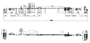
Checkpoint 1: Design – Turning Customer Requirements into Blueprints
The first step in equipment manufacturing is not material cutting – it’s drawing.
What type of cable will the customer produce? Loose‑tube, butterfly drop cable, or high‑fiber‑count? What is the target production capacity? Which country will the equipment be exported to (voltage and certification requirements vary)? Once this information is confirmed, the design team can begin work.
For an SZ stranding and cabling line, the core design considerations are the differential gearbox transmission scheme and the stranding head layout. A fully differential SZ stranding unit uses four servo motors for segmented drive – the first drives one cage section, the second drives two, the third drives four, and the fourth drives ten. This design offers a shorter transmission chain, smaller cage outer diameter, and smoother reversal compared to traditional single‑motor drive schemes.
For a sheathing line, the core design considerations are extruder screw selection and die matching. Different materials (PE, PVC, LSZH) have different requirements for screw structure and L/D ratio – these must be determined at the design stage.
After design drawings are completed, they undergo review – is the mechanical structure sound? Is the electrical control matched? Are the strength and service life of critical components up to standard? Only after the drawings pass review can the process proceed.
Checkpoint 2: Material Cutting and Machining – Turning Steel Plates into Components
Once drawings reach the workshop, the first task is material cutting.
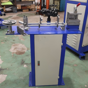
Frames, bases, stranding cages, differential gearbox housings – these structural parts may look rugged, but their precision requirements are far from low. The mounting surfaces of the frame must be machined on a gantry milling machine, with flatness controlled within 0.5 mm/m. The bearing bores in the differential gearbox housing are bored in a single setup on a machining center to ensure coaxiality between the two bearing bores.
Gears are the most critical components inside the differential gearbox. The manufacturing process: blank cutting → rough turning → gear hobbing → heat treatment (high‑frequency hardening) → precision gear grinding. High‑frequency hardening achieves tooth surface hardness of HRC 50–55, and precision grinding brings surface roughness below 0.8 μm. Harder and smoother – the gears are less prone to wear.
The extruder screw is made of 38CrMoAlA alloy steel and undergoes nitriding – at temperatures exceeding 500°C, nitrogen atoms diffuse into the steel surface, forming an extremely hard nitrided layer 0.5–0.7 mm deep, with hardness above HV 900. Without this nitrided layer, the screw would wear out after just a few months of extrusion under high temperature and pressure.
Checkpoint 3: Welding and Sheet Metal Fabrication – Building the Framework
With machined components ready, the next step is welding and assembly.
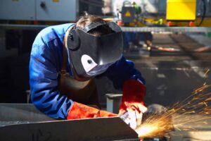
Frames, bases, and protective covers – these large components are cut from steel plates, then bent, welded, and assembled. Weak welds lead to frame deformation after long‑term high‑speed operation, causing guide rails to become misaligned and stranding precision to gradually drift.
Welding process matters. Hongkai’s frame welding uses CO₂ gas‑shielded welding, followed by aging treatment – naturally resting for a period to release welding stress, or heating in an aging furnace followed by slow cooling. Without aging treatment, welding stress slowly releases over time, and the frame deforms after a year or two of operation.
The cooling trough and take‑up base on the sheathing line are also welded components. The trough must be watertight, and the base must remain stable under the pulling force of the capstan.
Checkpoint 4: Electrical Assembly – Bringing the Equipment to Life
With the mechanical work done, it’s time for the electricals.
The control cabinet is the equipment’s “brain.” PLCs (Siemens or Mitsubishi), inverters, relays, circuit breakers – all are wired and labeled according to the circuit diagram. Every wire has a number that corresponds to the electrical schematic. Incorrect wiring can stop the machine – or worse, damage the inverter.
Sensor installation is also meticulous work. Tension sensors are mounted at the pivot shaft of the dancer arm – the angle must be correct and the mounting secure. Sensor signal cables must use shielded cables and be routed away from inverter output lines – otherwise, interference corrupts the signal and tension readings become inaccurate.
The laser diameter gauge requires even more care. It must be mounted after the cooling trough and before the first capstan, with the optical path perpendicular to the cable’s centerline. If misaligned, the measured outer diameter will be off, and the PLC will adjust sheath thickness incorrectly.
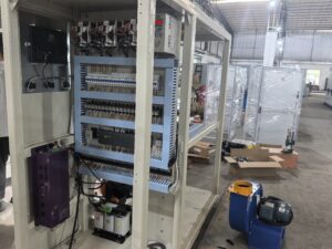
Checkpoint 5: Final Assembly and Commissioning – From Components to a Machine
After all components are machined and procured, they move to the final assembly workshop.
Final assembly is not “building blocks.” The coupling between the differential gearbox and the main motor must be aligned – deviation beyond 0.05 mm causes vibration and noise. The cage sections of the stranding unit must be coaxial – otherwise, tubes can’t pass through. The dancer arm must move freely without binding.
The first step after final assembly is no‑load trial operation. Power on, and each unit runs individually – does the pay‑off rotate? Does the dancer swing? Does the stranding unit reverse smoothly? Is take‑up traverse even? After individual units check out, run the entire line in coordinated no‑load mode – all units running as they would in production, verifying speed matching and signal communication.
Once no‑load runs pass, load trial operation begins – feeding actual tubes and sheath material for real production. GB 50950‑2013 specifies that equipment performance inspection must be conducted after load operation is completed. During load operation, a dynamic tension meter with accuracy no less than 1 N should be used to measure pay‑off tension fluctuation. Before leaving the factory, every Hongkai machine undergoes no less than 2 hours of load testing under simulated production conditions, with data recorded in the factory test report.
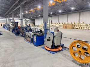
Checkpoint 6: Inspection and Factory Release – Every Machine Has Its Own “Health Report”
Passing the test run doesn’t mean it’s ready to ship – there’s one final step: inspection.
Every machine comes with a complete factory test report, listing:
-
Pay‑off tension fluctuation (Hongkai measured ≤ ±0.4 N)
-
Stranding pitch deviation (Hongkai measured ≤ ±0.08 mm)
-
Sheath concentricity (Hongkai measured ≥ 98.6%)
-
Sheath wall thickness tolerance (Hongkai measured ≤ 0.04 mm)
-
Noise, vibration, and temperature rise data for each unit
These figures are not arbitrary – they are actually measured by sensors and instruments during load operation. Customers can replicate the measurements upon receipt – if the numbers match, the equipment is qualified.
GB 50950‑2013 also requires that the acceptance report be completed in accordance with Appendix C, Table C.0.3 of the standard. Every machine also comes with electrical schematics, a PLC program backup on USB, bilingual operation manuals (Chinese/English), and a wear‑parts kit.
Manufacturing Lead Time
From material cutting to factory release, the standard manufacturing cycle for an SZ stranding and cabling line is 25 to 30 working days.
Machining and welding proceed in parallel – while the frame is being welded and aged, differential gears are being machined and the control cabinet is being assembled. After all components are completed, final assembly begins – assembly plus commissioning takes about a week. The final two days are dedicated to load testing and factory inspection.
Sheathing lines are slightly faster – 20 to 25 working days. The extruder assembly (screw, barrel, gearbox) has the longest machining cycle; other components can be produced in parallel.
For a complete line (stranding machine + sheathing line + auxiliary equipment), the standard cycle from contract signing to factory release is 45 to 60 days.
About Hongkai
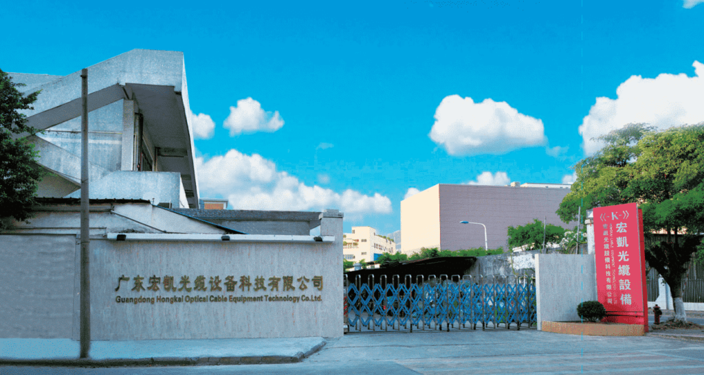
Guangdong Hongkai Optical Cable Equipment Technology Co., Ltd. began manufacturing wire and cable equipment in 2005 and was formally incorporated in 2015. Our main products include SZ stranding and cabling lines, fiber optic cable sheathing extrusion lines, and FTTH drop cable production lines.
From design to factory release, every Hongkai machine goes through the complete six‑step process. Key components – differential gears with high‑frequency hardening + precision grinding, 38CrMoAlA screws with nitriding treatment, SKF/NSK bearings, Siemens/Mitsubishi/Schneider electrical components. Every machine comes with a factory test report, a PLC program backup on USB, bilingual operation manuals (Chinese/English), and a wear‑parts kit. Our equipment has been exported to more than 15 countries and regions, with over 160 sets currently running on production lines worldwide.