SZ stranding is one of the most important processes in optical cable manufacturing because it directly affects cable quality, tensile performance, bending performance, and production stability. Based on the actual production operation process of optical cable stranding equipment, this guide explains the equipment composition, operation steps, core process control indicators, and common precautions of the SZ stranding and cabling production line, helping operators improve production efficiency and reduce operational mistakes.
Main Components of an Optical Cable SZ Stranding Production Line
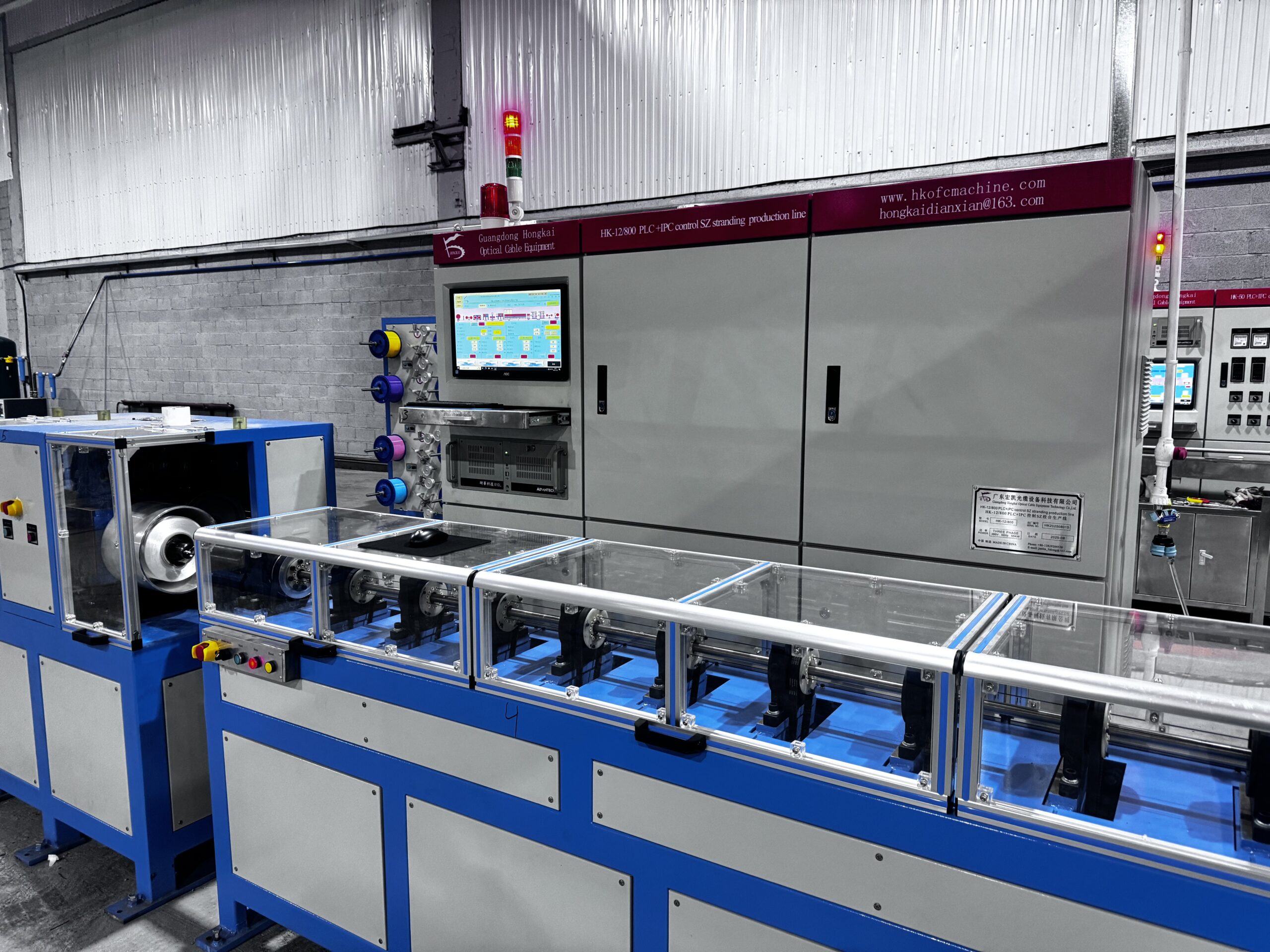
A standard optical cable SZ stranding production line usually includes the following equipment:
| No. | Equipment Unit | Function Description |
| 1 | Pay-off Rack | Carries and pays off strength
members (e.g., steel wire, FRP, etc.) |
| 2 | Pay-off Dancer | Adjusts pay-off tension to maintain
stable pay-off |
| 3 | 12-Way Loose Tube Pay-off Rack | Holds up to 12 loose tube reels simultaneously
for multi-fiber cable stranding |
| 4 | Gel Applicator | Fills water-blocking gel or fiber gel into the
cable core to improve moisture resistance |
| 5 | SZ Stranding Stand | Implements SZ (forward/reverse) stranding
to form the cable core pitch |
| 6 | Dual-Head Binder | First binding to fix the stranded cable core
structure |
| 7 | Taping Machine | Wraps polyester tape, water-blocking tape,
etc., to reinforce the cable structure |
| 8 | Single-Head Binder | Second binding to further secure the tape layer |
| 9 | (Capstan) | Provides stable pulling force and controls
line speed |
| 10 | Take-up Dancer | Adjusts take-up tension to ensure neat winding |
| 11 | Take-up Machine (Gantry Type) | Winds the finished cable neatly onto reels |
| Control Panel & System | PLC + Touch Screen | Centralized control of the entire line,
setting pitch, binding parameters, etc. |
Key Operation Steps and Precautions
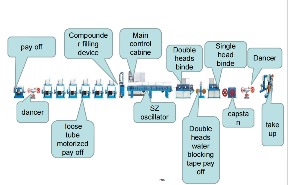
How to Use the Strength Member Pay-off Rack
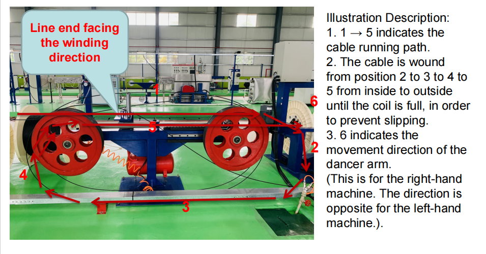
Wire end direction: The wire end must face the take-up direction to ensure smooth pay-off.
Width adjustment handle: Adjust according to reel width to center the reel.
Locking handle: Lock after adjustment to prevent vibration during operation.
Control panel: Controls pay-off start/stop and tension setting.
Pay-off Precautions (Key Points)
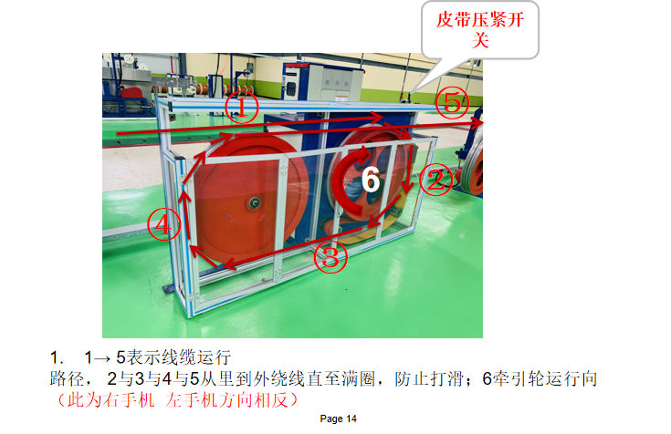
Correct threading path: Follow the sequence “1→2→3→4→5” from inside to outside until full, to prevent slipping. Note the dancer operation direction: right-hand and left-hand machines have opposite directions.
Reel pin alignment: The pay-off shaft pin must align with the reel limiting hole to prevent slipping during pay-off.
Tightening operation: Rotate the handle until the reel is firmly tightened to avoid loosening.
Lifting limit switches: Check the lift direction (up/down) is correct. Lifting operations are only allowed when the machine is stopped.
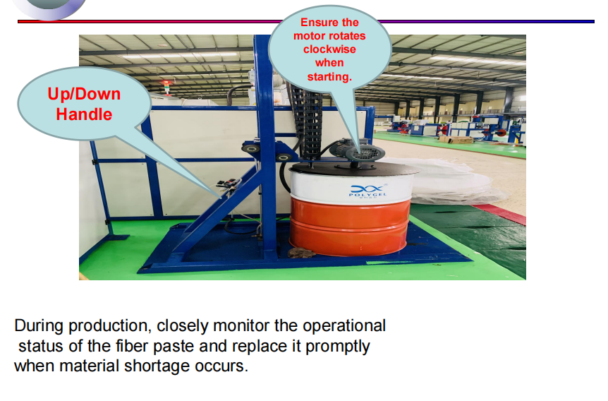
Motor start direction: Ensure the motor rotates clockwise (standard model).
Gel Applicator Precautions
During production, frequently observe the gel/fiber gel running status. Replace when low to avoid gel interruption or air bubbles entering the cable core.
SZ Stranding Stand Operation Points
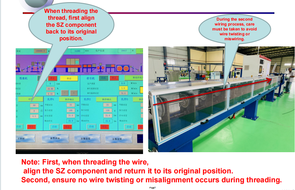
Return SZ to origin before threading: Prevent angle deviation after threading.
Avoid twisting or crossing loose tubes during threading: Each loose tube should pass through guide wheels in order without crossing.
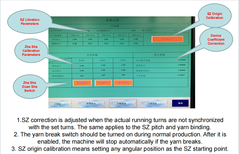
SZ calibration: If the actual stranding turns do not match the preset value, modify the SZ calibration parameter. The same applies to pitch and binding parameters.
SZ origin calibration: Can set any angular position as the SZ start point for convenient production changeover.
Dual-Head Binder and Single-Head Binder
Binding yarn installation direction: Incorrect installation may cause unstable yarn tension or yarn breakage
Yarn break switch: Must be turned on during normal production. When enabled, the machine will stop automatically upon yarn break, reducing waste.
Binding calibration parameters: Set binding pitch and tension according to process requirements.
Taping Machine Precautions
Taping direction: The wrapping direction (left or right) must match the stranding direction; otherwise, tape loosening or poor overlap may occur.
Caterpuller (Capstan) Operation
Threading path: Follow “1→2→3→4→5” from inside to outside until full to prevent slipping.
Running direction: Opposite for right-hand and left-hand machines; verify.
Belt pressure switch: Ensure proper belt pressure to avoid slipping that affects line speed stability.
Take-up Machine and Dancer
Gear shift mechanism: Select appropriate gear (large/small reel) according to reel size to match take-up torque.
Take-up dancer: Dynamically adjusts take-up tension to prevent uneven winding due to over-tightening or loosening.
III. Core Process Control Indicators for Cabling Process
The SZ cabling process plays a key role in optical cable manufacturing quality and production stability, with main purposes:
Improve cable flexibility and bending performance
Improve tensile strength
Enhance temperature characteristics
Support the production of optical cables with different fiber counts by combining different numbers of loose tubes
Three key process indicators to control:
| Process Indicator | Control Points |
| Cabling Pitch | Too small leads to insufficient fiber excess length; too large affects bending performance. Infinitely adjustable via PLC, fully differential structure ensures pitch stability. |
| Binding Pitch and Tension | Binding pitch must be uniform; excessive tension damages loose tubes, too
loose provides weak fixation. Segmented independent adjustment is optimal. |
| Pay-off and Take-up Tension | Tension fluctuations directly cause pitch deviation and fiber stress. Closed-loop
active pay-off recommended, fluctuation ≤ ±0.5N. |
Equipment Fault and Abnormal Handling
Driver/Inverter alarm: If resetting does not clear, check the alarm code. When an alarm occurs, disconnect power to the inverter/driver, then reconnect and reset to clear.
Meter calibration: When displayed length does not match actual length, use the formula:
F2 = F1 × (L2 / L1)
Where F1 = old meter coefficient, L1 = displayed length, L2 = actual measured length, F2 = new meter coefficient.
Operation Safety and Daily Maintenance Tips
1.The equipment must be stopped during lifting/reel change operations; never lift while running.
2.Regularly check the dancer arm flexibility to avoid tension jumps due to sticking.
3.Refill gel/fiber gel in time to prevent air ingress affecting water-blocking performance.
4.Keep yarn break switch on to ensure automatic stop upon breakage, reducing waste.
5.Equipment coefficients are factory-calibrated; non-professionals should not arbitrarily modify overall coefficient parameters.
Summary
Mastering the standard operation of the SZ stranding and cabling production line is the foundation for ensuring stranding quality, reducing waste, and improving production efficiency. From pay-off, dancer, SZ stranding, binding, taping to pulling and take-up, tension, pitch, and direction control at every step directly affect the mechanical and transmission performance of the finished optical cable.
Guangdong Hongkai Optical Cable Equipment Technology Co., Ltd. is a professional optical cable equipment manufacturer in China, specializing in a full range of optical cable equipment including SZ stranding and cabling machines, outdoor optical cable sheathing production lines, butterfly drop cable production lines, etc., providing whole-plant planning and overseas delivery services. For more equipment parameters or operation training, please contact us.